Hello again!
I’ve uploaded a simple-to-use color correction filter to github, so if you are a monogame or xna user be sure to check it out –> https://github.com/Kosmonaut3d/ColorGradingFilter-Sample
The description should be good enough to understand the setup, plus the solution provides sample implementations with a bunch of documentation inside.
Note of warning: This should all be taken with a grain of salt. As with many other things I do not copy reference implementations but go in “blindly”, do many mistakes and try to see how far it gets me. So unfortunately there will not be any links to resource papers and such; Google is your friend.
What is color grading?
Color Grading is a post processing effect that changes colors based on the transformation value in a look-up table (LUT) for this specific color (or another storage medium). This enables very wide range of processing for specific values, and can be used to shift colors, change contrast, saturation, brightness and much much more.
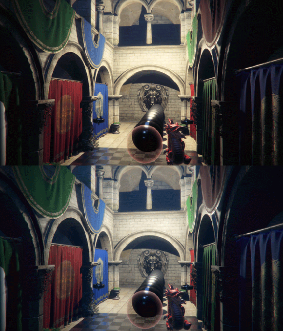
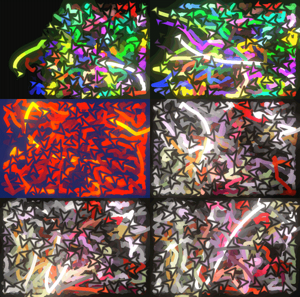 It can be used in subtle ways (see the gif above, where I just slightly adjusted curves and colors) or in very aggressive ways, totally transforming the original image as you can see on the right (saturated –> red/yellow gradient –> mute all colors but red).
Anyways, this thing is nothing special and has been used in film, image processing and even games for quite a while now.
I actually took a course at university where we transformed an image by transforming colors from one space to another (3d) space with giant look-up tables stored as three dimensional arrays. This process actually took minutes, but luckily I don’t have to rely on MATLAB and CPU power any more.
Look up tables
Color correction can work in different ways, even just multiplying the final image with a single color is some form of color correction.
Really good results, basically what you get with Photoshop and Premiere can be obtained by the use of LUTs. Large arrays that transform color spaces.
For example we can store a correspondent output color for every input color and define that our red (255,0,0) becomes a blue (0, 255, 0);
For a more comprehensive actual tutorial on how to create LUTs you should check out the readme on github.
The issue obviously is that we cannot store 255 x 255 x 255 different transformations (the amount of different colors with 8bit channels), since that would require too much memory and computing power.
By observing that most color transformations do not target specific color values, but rather a range of colors ( think “dark reds”) we are usually fine with storing only a subset of corresponding outputs and interpolate between them.
Since color has 3 channels (RGB) we basically need a cubic representation of color values, the axis being how much red, green and blue are in our color.
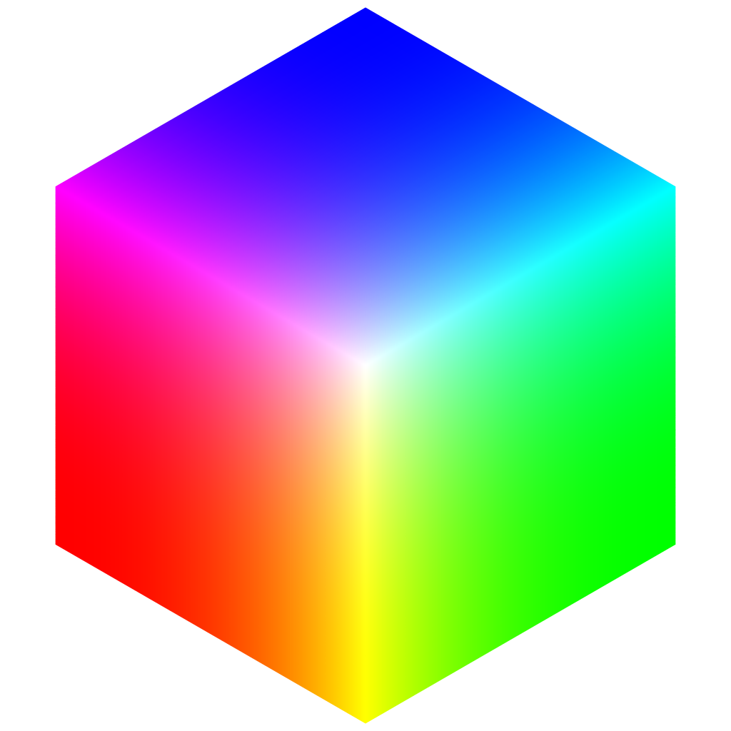
If we arrange the slices of this cube on a 2d plane a possible output looks like this:
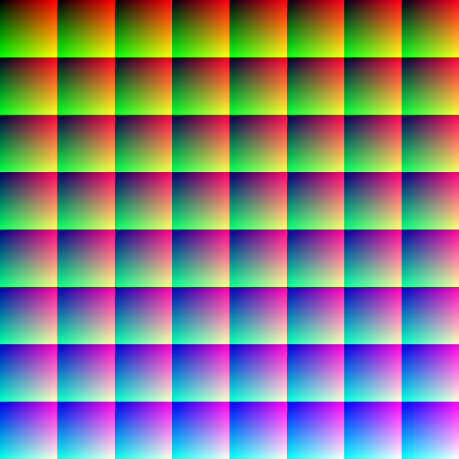
In this case each channel can assume 64 values, so we are basically compressing down 4:1.
You can see that for each block the red and green values form a [0,1][0,1] space and the blocks get progressively more blue.
If we move a little down to 32 values it looks like this (it’s not a square any more since the square root of 32 is not an integer number)
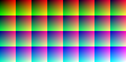
What I’m actually using though is an even more compressed variant: 16 values per channel. Quite harsh, but it turns out this is good enough in most cases.
When generating these LUTs I’ve made a few small mistakes at first though.
Correct Generation
This is the shader code I use to generate these look up tables.
float2 pixel = float2(trunc(input.Position.x), trunc(input.Position.y));
float red = (pixel.x % Size) / (Size – 1);
float green = (pixel.y % Size) / (Size – 1);float col = trunc(pixel.x / Size);
float row = trunc(pixel.y / Size);float blue = (row * SizeRoot + col) / (Size-1);
return float4(red, green, blue, 1);
The basic idea is to just use the current pixel’s position in our LUT texture to determine what color it should have.
Size in this case is the amount of values represented ( so for example 16).
SizeRoot is originally the root (so for example 4) but it’s more correct to say the root rounded down to multiples of 4. So for 32 it will be 4 too.
Note: On a CPU I would use a lot of integers, since we use truncated values anyways. However, many GPUs perform basic operations faster when using floats.
I think when looking at the code it is easily understandable. Let’s take red for example. We want our 16 pixels scale from 0 to 255, so our pixel locations are [0] to [15]. pixel.x % 16 will yield values between 0 and 15 and dividing that by (16-1) = 15 results in what we want –> [0..1] in red values from left to right.
However, I didn’t do this “correctly” from the start.
float2 pixel = input.Position.xy;
float red = (pixel.x % Size) / Size;
This is the original code. It should be noted that input.Position returns the pixel’s position on the rendertarget, so a value between [0,64]x[0,64] for example.
However, it returns the sampling position – so the top left pixel (which is stored as [0,0]) would have the position [0.5f, 0.5f]!
This means that the colors would not range from 0…255, but instead from 7 … 247 ( [0.5 … 15.5]/16 ). The computation afterwards would be correct for the values in between, since I made the same mistake there, but every value below 7 would just be rounded up to be at least 7 (same goes for brighter than 247)!
Correct Readback
The idea of LUTs is to read the input color and then look where it’s supposed to be found in the look up table and use the stored (manipulated) color value found there for the final output.
Obviously when we only store one value for a range of 17, we are bound to have bad artifacts.
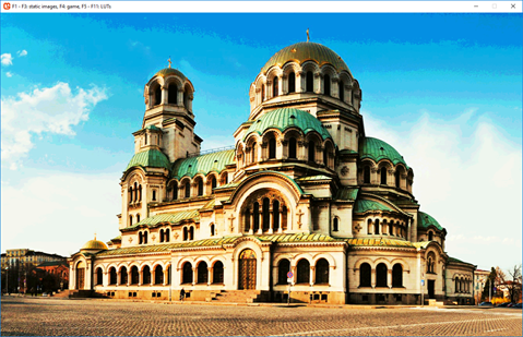 You can clearly see the banding on the sky.
The first idea is to just use hardware bilinear sampling when not on edges of the texture slices (We don’t want to “bleed” into a neighboring slice on our LUT).
This makes it better only for some color gradients (between red and green) but will not work for dark, light values AND any shifts in blue (different slice in the LUT).
So I did the next logical thing and implemented manual trilinear interpolation. I load the 4 pixel values around the sampling location and interpolate between them and I do the same for the next blue value (different slice) and interpolate between these results (in non-edge cases).
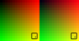
This results in smooth gradients across all colors – exactly what we wanted.
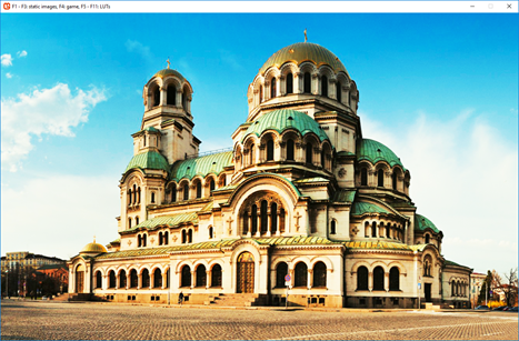
One thing that might be worth exploring – just convert our 2d texture to a 3d texture and use hardware linear filtering. We obviously want to store our LUT as a 2d representation so we can easily manipulate it with imaging software, but the renderer shouldn’t really care, should it? I’m not sure but that could possible be more cache-friendly, at least for large LUTs.
You can see the whole shader code in the source code on github, as always.
Performance and Quality
I’ve created 4 luts with channel dimensions of 4, 16, 32, and 64 respectively.
Note: This is the lut4 in it’s original size.
![]()
I drew the color graded version of the image onto a rendertarget of the original image size and then drew this rendertarget to the backbuffer.
I then compared performance to not using a LUT at all (drawing the image directly to the backbuffer).
The LUTs used were all neutral, so the colors should stay the same.
Quality
I made a screen shot of the original image and the color graded versions and compared them in an imaging program by using the “difference” modifier to see where they deviate. I then increased this error by multiplication and increase in contrast.
The results where overwhelmingly positive, in fact, I could not find a single error with the naked eye.
I wanted to post screen shots of each variant, but it turns out they are virtually impossible to tell apart (bar the one with 4 values).
The errors found are very very small even after repeating the error-pass 3 times and I don’t think it’s worth posting screens.
Even LUT4 performed pretty ok, given that it only has 8×8 pixels, but the error is visible enough to be obvious even in compressed gif form. There might be a computation error I think, in theory it could perform better, as the brightness values seem to not match very well.
To be fair, the default LUTs are more or less the perfect case for this kind of computation, since the values that have to be interpolated match the interpolation perfectly. (Red = 8 is the same as lerp(4, 12))
So I tried a heavily color graded version of the image and compared the desired look I wanted (directly captured in Photoshop) with the results in the program.
You can click on the images to compare them in different tabs.


I think the results are very good, but what’s more is that the difference between LUT16 and LUT64 are really small.
For the sake of comparison I’ve added my LUT4, too. The s-curves clearly get lost with the linear interpolation of values.
I’ve computed an error image and show the differences side by side.
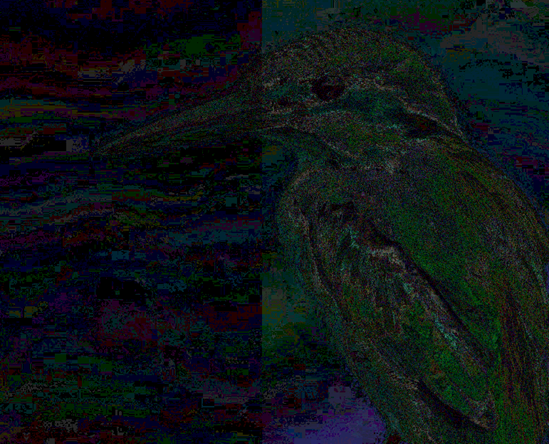
On the left is LUT64 and on the right is LUT16. This error image is exaggerated many times, but what’s clear is that basically all colors are slightly off, even if it’s a tiny margin. The difference between these two however, is, in my opinion, not relevant for real applications as you can see if you compare them with the final images above.
Performance
I didn’t write a millisecond counter fine enough to capture good averages with such high framerates, so I used FRAPS to capture the FPS and convert the round-about average to milliseconds.
The frame times are quite jumpy at such large frame rates, so I didn’t bother rounding to many decimals.
The results are as follows:
- No Color grading – 6150 FPS ~ 0.16ms
- LUT4 – 3550 FPS ~ 0.28ms
- LUT16 – 3550 FPS ~ 0.28ms
- LUT32 – 3500 FPS ~ 0.285ms
- LUT64 – 3250 FPS ~ 0.30ms
It seems the actual setup of drawing to another rendertarget alone is way more heavy than the size of the look up textures we are reading from, which was to be expected.
In an ideal application this would be merged with several other post process effects, so that the base cost of reading the input texture and storing new pixels is not relevant.
I can not say for certain after some tests that LUT4, LUT16 and LUT32 have relevant performance differences, which would favor 16 over 32 for example.
LUT64, which has a massive 512×512 texture, is noticeably slower.
So in conclusion, with my implementation, I’d say going for 16 or 32 is the right choice, as quality is pretty much on par.
I originally thought it might be a good idea to have the LUT32 only have 16 blue values (and 32 red, green ones) so it can be stored in cube. The human eye is not very sensitive to blues, so the reduction in quality might be ok for the potential gain in red/green quality compared to LUT16.
However, after seeing these results, I think it’s not worth the effort.
Final remarks
I am pretty happy with the results and confident that the filter is working as intended. I think it’s a great tool for artists to quickly adjust the look of their work without having to rework assets, so I think it has a place even for 2d “pixel art” type of applications.
I did check out Unity’s documentation as well as Unreal Engine 4’s Color Grading and I’m pretty happy to see that the look up tables seem to work the exact same way, except they store them in a strip instead of a cube. They also found 16 values to be sufficient it seems, but to be fair it’s really a good compromise of size and precision, as you can see in the sections above.
This is the default LUT for Unreal Engine:

EDIT: Turns out copying something directly from the browser changes the colors, I should have been more careful, I was wondering why some things were off.
After a second check the Unreal LUT is very much the same as the one I use, only stored in different dimensions.
The default LUT for Unity (at least in the documentation that states “legacy”) looks like this

It’s the same format as the Unreal one (256 x 16), but they are not using linear values between colors. Instead it seems like some gamma was applied beforehand, resulting in more dark and bright colors and less in between. The color range, however, is complete from 0 to 255 for each color.
EDIT:
I’ve checked some other engines, and here is the default LUT for Cryengine (http://docs.cryengine.com/display/SDKDOC2/Colorgrading+Tutorial)
Yes, it comes with the yellow/black border around it!
Like my own implementation of 16x16x16 they use a square of 4×4 tiles, but they also added three thick single-channel only gradients to the right.
However, these gradients are represented in the base 4×4 LUT, too (with lower precision of course) and I wonder if they are used at all when transforming.
I cannot think of ways that these can be useful, since they are only relevant to 255×3 colors, which are, realistically, not used that often (images rarely are composed of one-channel colors), plus it would render some pixels on the 4×4 LUT obsolete (along with possible pain in integration).
My guess is that, no, they are just a visual hint for the person who is color grading the image.


Great, I really like this article. Thanks.
Great article!
It has lots of pictures, which makes it easy to understand.
I have a few comments:
1. I don’t like your performance comparison.
You’re comparing no color grading and rendering to the backbuffer directly vs color grading to a temporary buffer and copying that to the backbuffer.
You’re comparing oranges to apples.
The only fair comparison would be to compare using no lookup table while still having the additional copy. Otherwise you’re just measuring the cost of copying the texture vs not copying it.
You could have also just color corrected the original image when you sampled it and rendered it to the backbuffer directly in all cases.
Without color grading you’d just sample the texture as is and perform no additional math.
2. Also using fraps to measure the performance can potentially be quite inaccurate, especially for such precise measurements.
You have to set up performance queries for any serious GPU time measurements.
3. The UE4 LUT image is down.
4. Have you done any research how color grading can be applied to an HDR framebuffer before tonemapping?
Hey Tara,
Thanks for reading. All your points are valid and it’s great feedback!
Some remarks on your points though:
@1. As written in the article “I didn’t write a millisecond counter fine enough to capture good averages with such high framerates, so I used FRAPS to capture the FPS and convert the round-about average to milliseconds.”
I didn’t really feel the need to put in the work for accurate tooling for this article. In my own future implementations I did in fact have some better frame (time) tooling, but I deemed the performance aspect of color grading not important enough back then.
@2. see 1
@3. I updated that to a new adress – thank you
@4. A bit, but not enough to write about it.